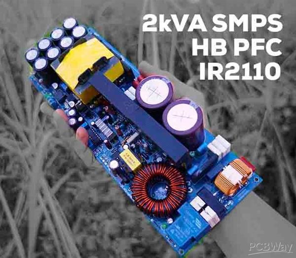
It's a 50Khz half bridge smps with the 300 volts of input voltage. So, I recalculated the transformer design and did a new winding. I checked every single part one by one, four or five times.

What would you suggest me to do? Maybe zenner diodes put reverted? (ExcellentIT calculations) I expected everything to run smoothly but after running it, all I get in the secondary output is +/- 2 volts!! Also the transformer makes an unpleasant noise. So, I used a 36v zener and as for turns ratio, (Primary 26 turns of 1.7mm ) and (Secondary 2X4 turns of.7mmX5) are my winding. The only difference is that I adjusted the circuit for +36/-36 volts. I built it using the exact same parts written in the schematic. Hello everyone, I made a 50Khz SMPS using the schematic I have attached to my message.

Feedback.i have shared the only tl494 circuit file. Of half-bridge SMPS circuit with SG3525 and IR2110 for. My name is Alex Dumais and I am an Applications Engineer for M - SG3525 is about power design - KA3525 Abstract£✭igital control switching power supply is the use of single chip microcomputer implementation of the switching power supply output vol.

Welcome to part 1 of the Introduction to the dsPIC® DSC SMPS family web seminar. DRM074 - Design of a Digital AC/DC SMPS using the 56F8323 Device. A MODIFIED PFC BOOST USED IN SABER A MODIFIED PFC BOOST USED IN SABER - Online UPS using the 56F8300.
SG3525 IR2110 SMPS RAR FILE DRIVER
Schematic diagram - ir2110 driver circuit, the optocoupler can be connected to control the motor, etc., can also be used to generate the PWM circuit chip.
SG3525 IR2110 SMPS RAR FILE WINDOWS
The related graphical interface windows as well as GDI+ transparent interface development - Power SMPS Schemtics Diagram Color - smps power supply circut using uc3842/45. independent component analysis is an important tool in signal processing.


 0 kommentar(er)
